



So, we experimented a bit on RF modules. This was just a general remote device built for testing different RF modules for transmission (Tx), but if you were to look closely, 315 MHz pairs were used. They're extremely cheap even back in 2017.
However, they are extremely prone to noise and had to be coded very tightly. I remember having to use Manchester protocol for the modulation, with double-redundancy polling. Sadly, the source files are not here. Later, a simple microcontroller board was designed and printed for the Tx.
Did I hear someone say "Why are you not using Xbee"? Because one pair costs RM300 back then.

Next was the interface. At a time when easily accessible touch screens existed, Raspberry Pis were the OG. The interface was programmed with PyQt, which had a good forum community to help out in the development.
In short, PyQt allows the display of GUI to send digital data to the microcontroller via the Raspi GPIO pins. We sent the data from 8 pins, which was crude but it did the job. The flow was: transfer 0xF0 from Pi to the Tx microcontroller GPIOs. A simple bit hifting converts the value to hex for transmission.
For the receivers which light up and blare noise (10 units were made, and I think we used PIC16F1455) to read the 8-bit data in hex. And internal oscillator-enabled!
This GIF is an actual footage of me testing the system. But I've uploaded the video too!
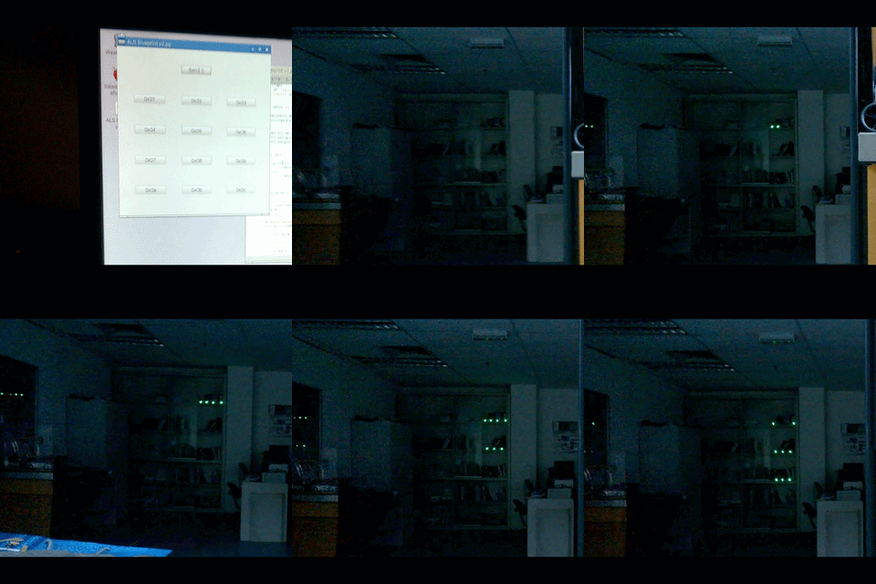
Next was the interface. At a time when easily accessible touch screens existed, Raspberry Pis were the OG. The interface was programmed with PyQt, which had a good forum community to help out in the development.
In short, PyQt allows the display of GUI to send digital data to the microcontroller via the Raspi GPIO pins. We sent the data from 8 pins, which was crude but it did the job. The flow was: transfer 0xF0 from Pi to the Tx microcontroller GPIOs. A simple bit hifting converts the value to hex for transmission.
For the receivers which light up and blare noise (10 units were made, and I think we used PIC16F1455) to read the 8-bit data in hex. And internal oscillator-enabled!
This GIF is an actual footage of me testing the system. But I've uploaded the video too!

On D-day, we demo-ed the system to our clients. On the table is the system in a plastic casing, the Raspberry Pi with the display all in place. Powered with a 12V DC supply. The room rang and rang from the buzzers which was really annoying. But all worked well.
Before the demo, I remembered that the whole thing kept on rebooting. Then we discovered that the 5V regulator (an LM7805) for the Pi was overheating, with the use of a thermal camera.
Funnily enough, Bad (the one presenting the stuff, and the one responsible for the PCBs) was the one suggested that we use three regulators in parallel. Which made me think "Huh?!!" . But it worked. But it was still running really hot. Nowadays there are really cheap and efficient buck regulator modules. Not during our time.
Seems like they won an award for this project.

Here's a funny story though, and it's 100% true.
When me and Bad left the building, we entered the car. As I shifted into the reverse gear, the car (as any car would be) made a beep. I was startled by this sound and looked at Bad, who in turn looked at me, equally surprised.
"I thought the beep came from those devices!" I said. "Me too!" said Bad. We had a good laugh that day.
Author: AH Poh, 22 May 2026
*Note: To aid the viewer's perspective, we added weightage W, followed by a number, which states the estimated number of sub-projects within it.
Usually, one project has several major facets which need to be dealt with separately from the others before they converge as a single. A medical device generally has the most facets due to the multidisciplinary aspects, including embedded programming, electronics, optical alignment, prototyping design and aesthetics, and also interface programming, hence, W = 6.
This highlights that the entries presented are all significant, though not equally so, and that each is distinct.